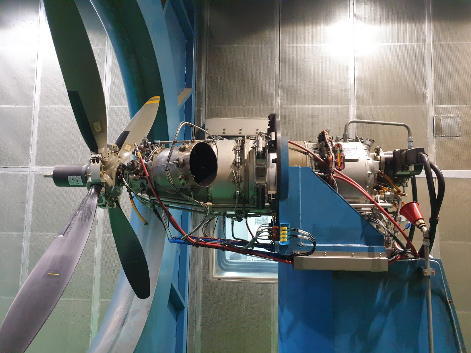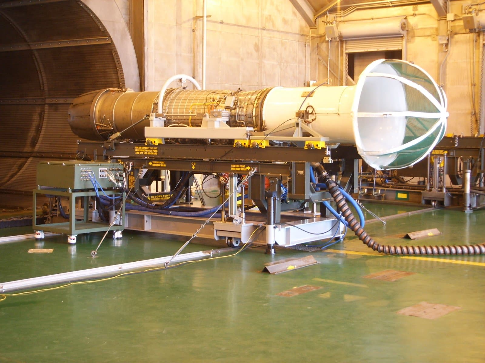
Turboshaft Engine Test Facility
Turboshaft Engine Test Cell, KUH Engine Test Facility Construction, Lynx Engine Test Bed
A test facility project in which GENEQ designed and built a dedicated turboshaft engine test cell, from the fuel, cooling, air and power supply systems to the test stand, dynamometer and control and instrumentation system. GENEQ also designed and built a mobile engine test bed made up of three containers (control, test and supply) for post-maintenance performance testing of the GEM 42 MK1017 engine fitted to the Lynx helicopter.
Turboshaft engine test facility
Verifying the performance and safety of an installed engine on the ground requires a dedicated test facility in which the fuel, cooling water, air and power supply systems, the test equipment that holds the engine and applies load, and the control and instrumentation system that acquires and manages test data all work together. GENEQ carried out the entire process, from design through fabrication and installation, for the turboshaft engine test facility operated by the Army Aviation Maintenance Group.
Facility configuration
The facility consists of three main areas.
Area | Role |
|---|---|
Engine test facility | Infrastructure that reliably supplies fuel, cooling water, air and power |
Engine test equipment | Mechanical equipment that holds the engine, applies load and measures performance |
Engine control and instrumentation system | System that monitors and controls the facility systems and acquires and stores engine data |
Five packages of the engine test facility
Fuel supply package
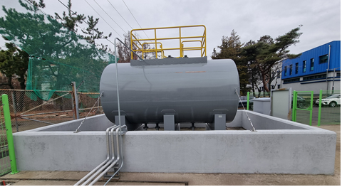
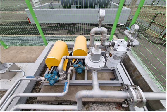
Alongside a large-capacity fuel tank, GENEQ designs and builds a fuel supply package that continuously delivers uncontaminated fuel at constant pressure, and a precision flow measurement package. A fuel leak test package using fluorescent oil and a preservation oil supply package for engine corrosion protection after run-up are also included to protect the engine.
Cooling water supply package
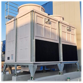
A large-capacity cooling tower system is designed and installed to handle the heat generated by the engine and dynamometer. An emergency water supply system for interruptions in cooling water supply and cooling water condition monitoring sensors are built in to secure stable facility operation.
Air supply and starting air package
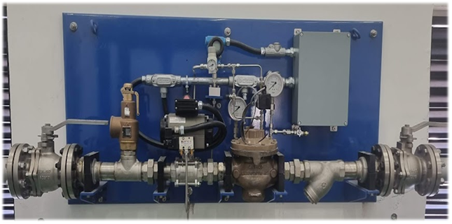
GENEQ builds the system that supplies compressed air for engine starting and the various utility systems, together with a starting air package that regulates supply precisely to the engine's required starting pressure.
Power supply package
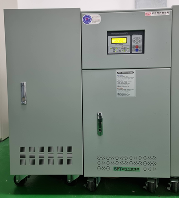
Power systems for large drive units and for precision control devices such as servo motors and valves are designed separately by purpose. The control and instrumentation system has its own uninterruptible power supply (UPS), so that a fault in one system does not affect other systems or the test data.
Noise reduction package
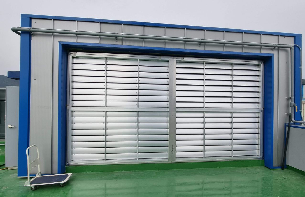
To meet the noise regulations for test cells, GENEQ designs, builds and installs acoustic panels at the intake and exhaust, steel wall cladding that protects the building exterior from hot exhaust air, and acoustic doors and observation windows.
Engine test equipment
Test stand and engine test adapter
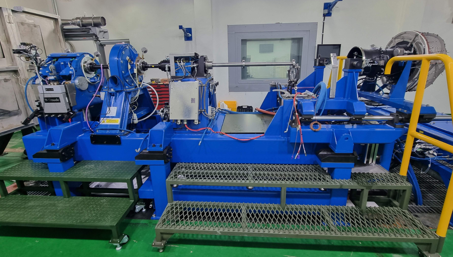
GENEQ builds a test stand with interchangeable adapters for different engine types, and a test adapter designed specifically for the target engine. It includes the mount assembly and alignment structure for installing and securing the engine, along with a structure that safely collects the oil released when the engine is fitted or removed, improving maintenance safety and convenience.
Dynamometer package
A dynamometer package that absorbs engine output and allows testing at the required load conditions is procured and installed. An auxiliary device that simulates rotor inertia and a dedicated controller are integrated to create a test environment close to actual operating conditions.
Torquemeter assembly
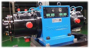
Consisting of the torquemeter, signal processing unit, couplings and a dedicated lubrication system, it measures engine output precisely.
Engine control and instrumentation system
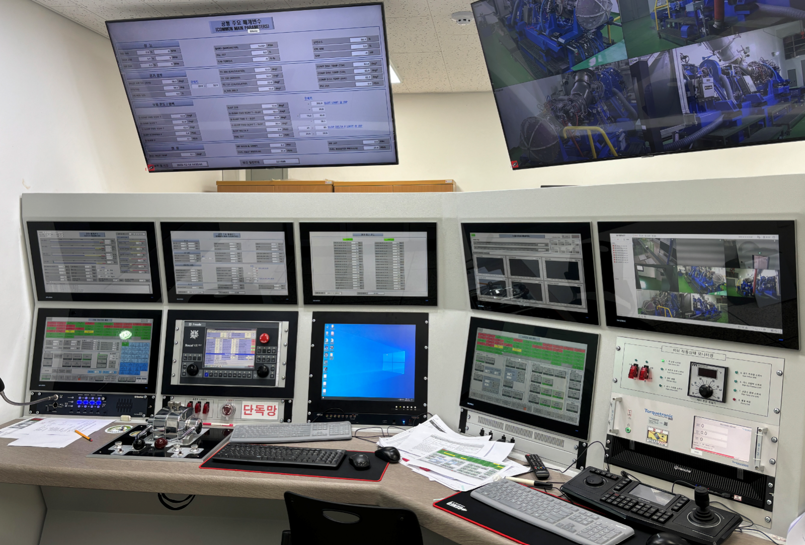
GENEQ designs the distribution and control systems that relay power and control signals to each package, and builds the control console desk and instrumentation cabinets so that engine pressure, temperature and vibration data can be acquired and stored in real time. The operating software was developed in-house with separate functions for test operation, monitoring and vibration measurement, letting operators check engine status on the screen that suits their task.
Operation, calibration and maintenance framework
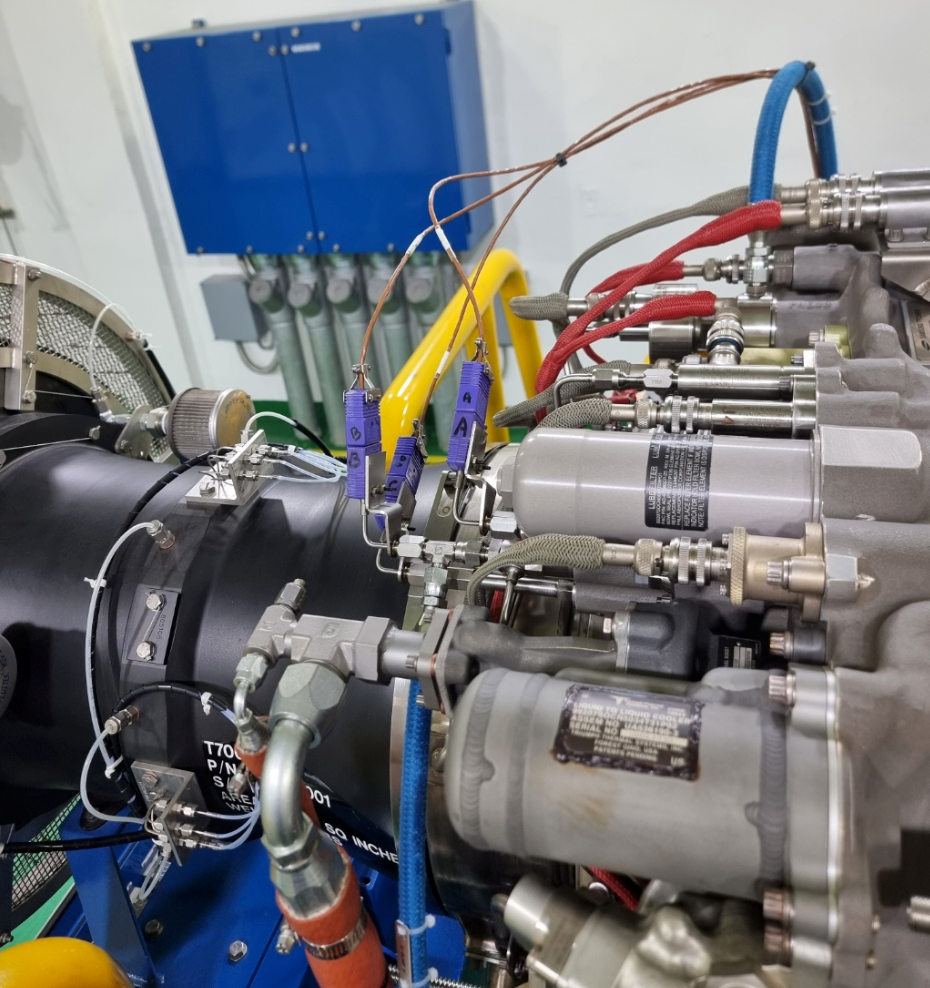
Alongside the facility itself, GENEQ establishes an operating framework covering power-up and shutdown procedures, periodic calibration procedures for key systems such as pressure, temperature, speed, vibration and torque, system-level fault diagnosis and replacement procedures for major consumables. This gives maintenance staff the basis to operate the facility reliably after handover.
GENEQ's test facility capability
Designing, building and installing every system of an engine test facility, from the fuel, cooling, air and power supply systems to the engine mounting and load test equipment and the control and instrumentation system for data acquisition, demands comprehensive engineering capability. Through the engine test facility project, GENEQ has proven its capability as a specialist in large test facilities for the defense sector.
Containerized mobile engine test bed (Lynx)
After a helicopter engine has been serviced or a module replaced, its performance must be verified on the ground before it is refitted to the aircraft. For the GEM 42 MK1017 engine fitted to the Lynx helicopter, GENEQ designs and builds a mobile engine test bed that supports functional testing and adjustment before installation, performance testing after inspection and module replacement, and fault diagnosis. Instead of a fixed test building, it is configured as containers that can be moved to and installed wherever they are needed.
A test system in three containers
The test facility separates the three functions of control, testing and supply into individual containers.
Container | Role |
|---|---|
Control container | Central control area for controlling and monitoring the engine and auxiliary systems |
Test container | Area where the test bed and engine actually run |
Supply container | Area that supplies the fuel, water and air needed for testing |
Each container is designed as a welded steel structure with weather-resistant coating for durability in outdoor operating environments.
Control container
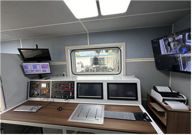
The control container is the test operations area, housing the equipment for controlling and monitoring the engine and auxiliary systems in one place. Its design accounts for noise and insulation so that staff can work comfortably for long periods. For operating efficiency and convenience, the control console is ergonomically arranged for two operators working at the same time. The console is placed next to the observation window so that operators can watch the engine directly while checking measurement data.
It also integrates the main equipment needed for test operations, including the power supply and distribution units, uninterruptible power supply (UPS), data acquisition and processing system, temperature and humidity control system, and dynamometer control system, supporting a stable and efficient test environment.
Test container
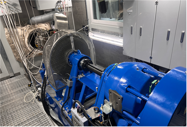
The test container houses the test bed and the engine power control unit. The test bed consists of a base frame and a dynamometer, and generates the load required for engine testing.
Air for engine operation enters through an intake system with noise-reducing baffles and intake louvers, and hot exhaust gas is discharged outside through an exhaust system made of heat- and corrosion-resistant materials. Engine output is controlled by a condition lever that regulates fuel flow and a lever that selects free turbine speed, and the engine under test can be observed directly through the observation window.
Supply container
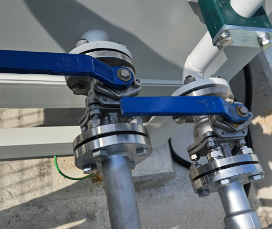
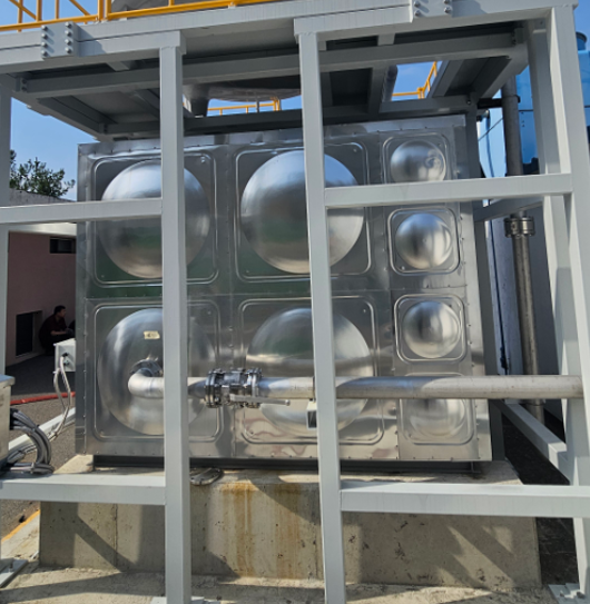
The supply container provides the fuel and water needed for testing. The fuel supply system consists of a water separator, an outdoor fuel tank with level measurement, and a fuel package, with fuel flow, pressure and temperature displayed in real time. When the engine is not in use, preservation oil can be circulated instead to prevent corrosion.
The water supply system delivers cooling water to the dynamometer so that load can be applied to the engine. Water from the outdoor tank passes through the dynamometer, is cooled again in the cooling tower and recirculated. Heating to prevent freezing in winter and real-time level monitoring are also provided.
Supply and service systems
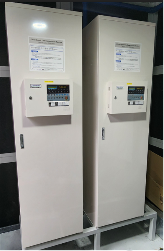
For the safety and operating convenience of the whole test facility, GENEQ provides power supply and distribution, zoned lighting, fire suppression, emergency stop, heating, cooling and ventilation, and internal communication systems as a complete set. The fire suppression system uses a clean extinguishing agent to minimize equipment damage in the event of fire, and can be operated both manually and automatically. The power system includes an uninterruptible power supply (UPS) so that operators can shut the engine down safely even if the main power fails.
Instrumentation and control system
The engine test system consists of the instrumentation system, computer hardware and dedicated software, and acquires and processes data throughout the test. From the control console, operators manage the entire sequence consistently, from test preparation and functional checks to test operation and system shutdown.
GENEQ's test facility capability
Integrating control, test and supply functions into a single mobile containerized system, rather than a fixed test building, demands the design capability to cope with a wide range of site conditions, space constraints and installation environments. Through the containerized mobile engine test bed project, GENEQ has built comprehensive engineering capability not only in fixed test facilities but also in mobile test facilities tailored to site requirements.